
How to Cut Internal Keyways — Step-by-Step Guide
Cutting an internal keyway correctly requires the right method for your bore geometry, the right tooling for your material, and a setup that holds centerline through the full depth of the cut. Get any of those wrong and you’ll either scrap the part or end up with a keyway that fails under load.
This guide walks through the full process — method selection, setup, execution, and troubleshooting — for the three practical methods of cutting internal keyways: keyseat milling, broaching, and wire EDM. It covers both manual machine and CNC applications.
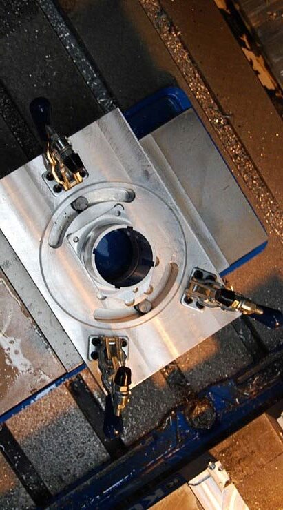
What Is Required to Cut a Keyway?
Before cutting begins, several key factors must be determined:
Bore diameter and depth
Blind or through-hole configuration
Required keyway width and depth
Material type and hardness
Tolerance requirements
These factors influence both tooling selection and machining method.
Tools Used to Cut Internal Keyways
Several machining processes can be used to cut internal keyways. The most common include:
Broaching tools
EDM electrodes
Slotting/shaping tools
Keyseat milling cutters
Each method removes material differently and is suited to specific production needs.
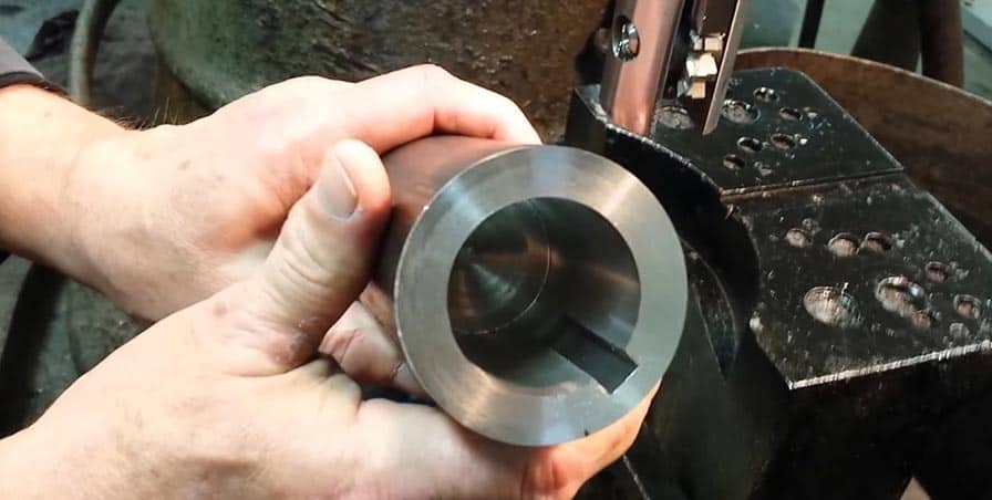
Step-by-Step: How to Cut Internal Keyways
The exact steps vary by machining method, but the overall process follows a similar structure.
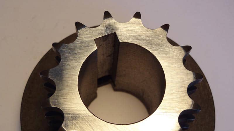
Step 1 — Choose the Right Method for Your Application
Before anything else, your bore geometry and material determine which methods are viable. Starting with the wrong method wastes time and risks the part.
Use keyseat milling if:
- The bore is blind with no relief hole, undercut, or cross-hole at the end
- The keyway dimensions are non-standard and no off-the-shelf broach exists
- The material is hard (above ~35–40 HRC) where broaching becomes impractical
- The run is short — one to a few dozen parts — where custom broach economics don’t work
- You need to complete the keyway on your existing CNC without a part transfer
- The bore has complex geometry — steps, threads, internal shoulders — that block a broach
Use broaching if:
- The bore is a through bore with no blind end
- The keyway size is standard and an off-the-shelf broach exists for your bore diameter
- The run is high-volume and the fixed tooling cost is justified
- The material is mild steel, aluminum, bronze, or other soft alloy below ~35 HRC
Use wire EDM if:
- No mechanical method is feasible — typically very hard materials above ~50 HRC or unusual geometry that no cutter can be designed for
- Accept the slow cycle time and high per-part cost as necessary for the application
When in doubt for a blind bore, non-standard dimension, or difficult material — keyseat milling is the answer in most cases.
Step 2 — Gather Your Dimensions and Verify the Print
Before ordering tooling or setting up the machine, have these dimensions confirmed from the part drawing:
- Bore diameter — the finished bore diameter the keyway tool will seat in. If the bore hasn’t been machined yet, confirm the finished diameter before ordering tooling.
- Keyway width — the dimension across the slot. Verify the fit class (Class 1 free, Class 2 normal, Class 3 close) and the tolerance — typically +0.000″/+0.002″ for a normal fit.
- Keyway depth — measured from the bore wall surface to the bottom of the slot. This is the radial depth, not total slot height.
- Keyway length — how far the slot extends axially into the bore. For blind keyways, this is the distance from the bore entry to the end of the slot.
- Angular position — where the keyway is located relative to a datum on the part. Critical for assemblies with multiple keyways or indexed components.
- Key standard — ANSI B17.1 for inch series, DIN 6885 or ISO 773 for metric. Confirm the standard and key number your print references.
- Material and hardness — what the part is made of and its condition (annealed, pre-hard, heat treated). This determines cutter selection.
- Surface finish callout — keyway surfaces typically require 125 RMS or better for standard applications; tighter for precision fits.
If any of these dimensions are unclear or missing from the print, clarify before cutting. A keyway in the wrong location or wrong width means a scrapped part.
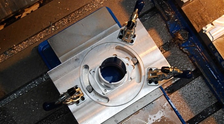
Step 3 — Select and Order Your Tooling
For Keyseat Milling
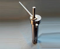
NMT keyseat millers are custom-manufactured to your bore diameter and keyway dimensions. To order:
- Confirm your bore diameter, keyway width, keyway depth, and keyway length
- Specify your material and any hardness information
- Indicate whether the bore is blind or through
- Specify your machine type — manual drill press, manual mill, or CNC (horizontal or vertical)
- Submit via the RFQ form or call 513-541-6682
Custom tooling ships in 2–3 weeks. Stock-size tools ship in 2–3 days. The tool arrives ready to run for your specific application — no on-machine adjustment required.
For Broaching
- Confirm your bore diameter and keyway dimensions against standard broach size charts (ANSI B17.1 dimensions)
- Order the appropriate push or pull broach and guide bushing for your bore diameter
- Confirm you have a broaching press or hydraulic press capable of the required tonnage
- For non-standard dimensions, obtain a quote for a custom broach — factor in 4–12 week lead time
For Wire EDM
Wire EDM is typically outsourced to a shop with the equipment. Provide your part print and discuss setup requirements, fixturing, and lead time directly with the EDM shop.
Step 4 — Set Up the Machine
Keyseat Milling Setup — Manual Machine (Drill Press or Mill)
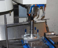
- Mount the part securely. The part must be clamped so it cannot rotate during the cut. For round parts, use a V-block with a clamp or a dedicated fixture. The bore must be oriented vertically (drill press) or horizontally (mill) depending on your setup.
- Insert the tool into the spindle. The keyseat miller mounts in a standard drill chuck or collet. Tighten securely — the tool should have zero lateral play in the chuck.
- Align the tool to the bore. Lower the tool into the bore slowly. The pilot section seats against the bore wall and self-aligns — the bore guides the tool, no external alignment fixture is required. Confirm the tool drops in freely with a close sliding fit before starting the spindle.
- Set spindle speed. Refer to the NMT feeds and speeds chart for your model number and material. Start at the lower end of the RPM range for the first cut. Most NMT keyseat millers run between 350 and 1,900 RPM depending on size and material.
- Apply cutting fluid. For steel, stainless, and hard alloys, apply cutting oil at the bore entry before starting the cut. Cast iron runs dry or with an air blast.
- Set the angular position of the keyway. Rotate the part (not the tool) until the keyway will be cut in the correct angular location. Lock the part in position.
Keyseat Milling Setup — CNC Machining Center
- Load the tool into the carousel. The keyseat miller mounts in a standard tool holder — ER collet chuck, hydraulic holder, or similar — appropriate for the tool shank diameter. Confirm with NMT if you’re unsure of the correct holder for your spindle interface.
- Set the tool length offset. Measure the tool length and enter the offset in the tool table. The reference point is typically the bottom of the pilot or the cutter centerline depending on how your program is written.
- Write or confirm the program. The keyway operation is a tool change followed by an axial (Z-axis) feed move into the bore. The spindle runs at the programmed RPM, the tool indexes to the bore position, and the Z-axis feeds at the programmed rate. No complex toolpath is required — it’s a straight axial feed.
- Confirm coolant. Program coolant on for steel and hard alloys. For cast iron, coolant off or air blast.
- Set part datum and angular position. The keyway angular position is set by the part fixturing or rotary axis position. Confirm this before the first part.
Broaching Setup
- Install the guide bushing in the bore, aligned so the broach will be guided on centerline.
- Set the part on the broach press fixture so the bore is aligned with the ram.
- Lubricate the broach and bore with broaching oil or paste.
- Position the broach through the bushing, aligned with the keyway angular position.
- Set the press stroke to match the broach length plus clearance.

Step 5 — Execute the Cut
Keyseat Milling — Manual
- Start the spindle at the selected RPM.
- Apply cutting oil at the bore entry.
- Feed the quill (drill press) or Z-axis (mill) downward at a smooth, consistent rate. Do not hesitate or dwell — maintain continuous feed pressure.
- Feed to the programmed depth — watch the depth stop or DRO.
- At full depth, stop feeding. Retract the quill or Z-axis smoothly.
- Stop the spindle before removing the tool from the bore.
- Inspect the keyway — width, depth, and surface finish — before removing the part from the fixture.
Keyseat Milling — CNC
- Run the program from a safe starting position.
- Confirm the tool change executes correctly and the tool is seated.
- Watch the first part through the keyway operation — confirm chip formation, listen for chatter, verify the feed rate feels appropriate for the material.
- After the first part, measure the keyway width and depth before continuing the run.
Broaching
- Apply broaching compound to the broach teeth and bore.
- Start the press stroke slowly — confirm the broach is entering straight before applying full force.
- Complete the stroke in one continuous movement — don’t stop mid-stroke.
- Remove the broach and inspect the keyway.
Step 6 — Inspect and Measure
After cutting, measure the keyway before removing the part from the fixture:
Width: Use a precision keyway gauge or gauge pin set. For a Class 2 normal fit, the keyway width should be the key width +0.000″/+0.002″. If width is undersized, do not attempt to re-cut — check setup and consult NMT if the tool appears to be cutting narrow. If oversized, the keyway will need to be evaluated against the fit requirements.
Depth: Use a depth micrometer referenced from the bore surface. Confirm depth matches the print callout within tolerance.
Length: For blind keyways, confirm the slot terminates at the correct depth into the bore and that the end of the keyway is clean.
Surface finish: Visually inspect for chatter marks, built-up edge on the walls, or torn material. A good keyseat-milled keyway has clean, flat walls with no tool marks perpendicular to the cut direction.
Angular position: For indexed keyways, verify angular location with a protractor, sine bar, or CMM depending on the tolerance requirement.
Cutting Keyways in Blind Holes
Blind bore keyways present unique challenges because the cutting tool cannot pass completely through the part.
Methods suitable for blind bores:
EDM
Keyseat milling
Broaching is typically not an option for blind holes because the broach requires clearance to pass fully through the bore.
For many applications, keyseat milling provides the best combination of flexibility and control when cutting blind bore keyways.
Step 7 — Troubleshoot If Needed
Keyway width is oversize: Most common cause: spindle runout, loose pilot fit, or driving pins not fully engaged. These are setup issues. Check all three before adjusting anything else. If the tool is running true and width is still oversize, contact NMT — the cutter may have worn.
Keyway width is undersize: Less common. Can result from cutter deflection in hard materials or a tool that wasn’t manufactured to the correct width. Measure the cutter directly and contact NMT.
Chatter marks on keyway walls: Check pilot fit first — a loose pilot is the most common cause. Then check driving pin engagement and spindle runout. If setup is good, reduce RPM 10–15% and slightly increase feed rate. Running too slow with too light a feed causes rubbing and chatter in many materials.
Chip packing in blind bore: Reduce feed rate and apply cutting oil at the bore entry. In deep blind bore applications, retract the tool periodically to clear chips before continuing.
Cutter wear faster than expected: Running too fast in hard material is the most common cause. Confirm RPM matches the feeds and speeds chart for your model and material. Ensure cutting oil is being applied. Dull cutters can be resharpened — contact NMT.
Part moving during cut: Inadequate fixturing. The part must be clamped so it cannot rotate under cutting torque. For round parts in a V-block, the clamp must prevent rotation — don’t rely on V-block friction alone.
Common Internal Keyway Machining Mistakes
Not verifying bore diameter before ordering tooling. The keyseat miller pilot is sized for your specific bore. If the bore is out of tolerance or the print dimension was misread, the tool won’t fit or will be sloppy. Always measure the finished bore before ordering.
Attempting to broach a blind bore. A push broach without a relief groove at the end of the bore will jam. If the bore is blind, broaching is not the right method — use keyseat milling.
Running too fast in hard material. The temptation to run at mild steel speeds in 4140 pre-hard or stainless leads to rapid cutter wear and poor finish. Use the hard steel RPM values from the feeds and speeds chart and apply cutting oil.
Not checking angular position before cutting. Once the keyway is cut, angular position errors can’t be corrected without scrapping the part. Verify the fixture orientation before the spindle starts.
Cutting the keyway before the bore is finished. The keyseat miller pilot seats against the bore wall to guide the cut. If the bore is still at rough dimension, the pilot won’t fit correctly and the keyway won’t be located accurately. Finish the bore to print dimension first.
When to Use Keyseat Milling
Keyseat milling is often preferred when:
Machining blind bore keyways
Producing low to medium batch sizes
Requiring flexibility for varying dimensions
Minimizing tooling investment
Because material is removed incrementally, machinists can fine-tune dimensions during the cutting process, making keyseat milling particularly valuable for precision applications.
About NMT Keyseat Millers
National Machine Tool has been manufacturing custom keyseat millers for internal keyway applications since the early 1900s. Our tools are custom-made to your bore diameter and keyway dimensions, ship in 2–3 weeks, and run on equipment you already have — manual drill press, manual mill, or CNC machining center.
If you have a keyway application that’s giving you trouble — blind bore, hard material, non-standard dimension, or complex geometry — contact us. We’ve likely seen something similar before.